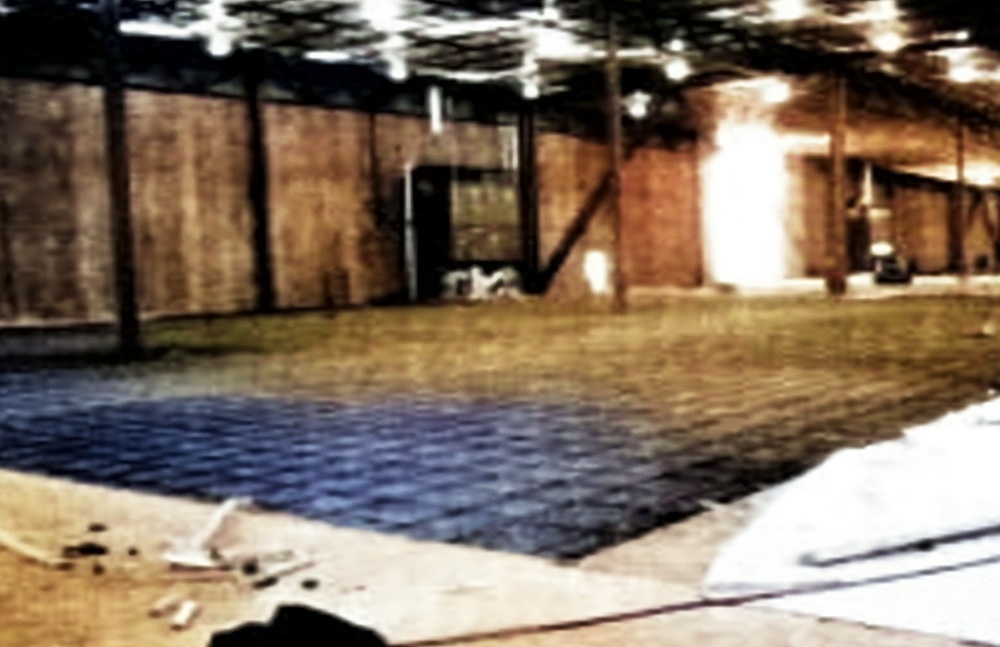
When selected by the Quaker Oats Company, makers of Gatorade, to provide engineering services for the new Gatorade Southwest Facility in Atlanta, Georgia, the design-build partnership of Metric Constructors and Lockwood Green Engineers and Architects opted for a state-of-the-art design that would use cutting-edge technology where possible. This decision would ensure a design that accommodated the many specialized functions of the bottling/warehouse facility and would eliminate or minimize the problems that occur in most typical industrial floor construction. Gatorade and Metric Constructors agreed to use the most advanced, state-of-the-art techniques and materials possible; furthermore, Gatorade and Metrick fostered a spirit of teamwork with all project participants, a cooperative endeavor that lead to a number of excellent ideas. Because of time constraints, a fast-track method of design and construction was adopted. Although the project had many special features – such as attractive precast concrete wall panels, split face concrete block, tall concrete block masonry partitions, and continuously reinforced portland-cement concrete (PCC) slabs where floors were to be covered with finishes (toppings, VCT) – the feature that set this project apart from other facilities of this type was the unique shrinkage-compensating concrete floor with joints as far as 125 ft (38 m) apart with no significant cracking.
The focus of this article is on some of the unique features of the Gatorade facility’s floors, which are significantly different from typical bottling or warehouse facility floors and even far from many previously constructed high-quality floors. The final design of the floors specified over 415,000 ft. (38,000 m2), most of which were of shrinkage-compensating concrete, the design and construction of which incorporated the most advanced techniques were combined in ways never previously used to create floors of this type.
What is shrinkage-compensating concrete?
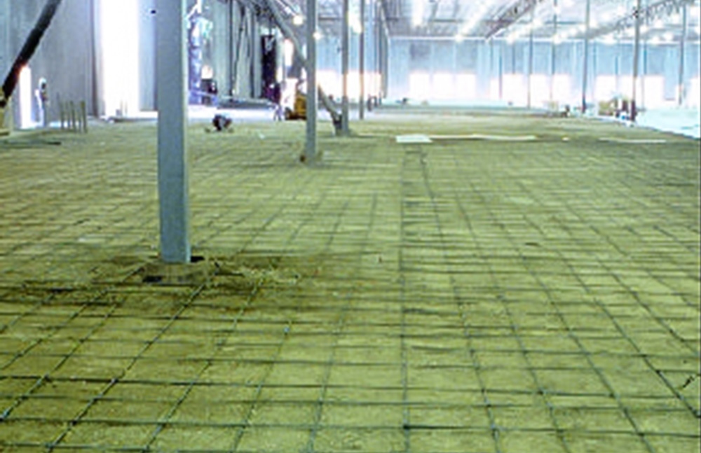
Shrinkage-compensating concrete (SCC) is made with a special cement (called Type K) or an additive component that causes a volume increase of the concrete after settling. If the SCC is properly and elastically restrained, it induces compressive stresses in the concrete that are intended to approximately offset the tendency of drying shrinkage to induce tensile stresses. In SCC floors, properly sized reinforcing steel (not too much and not too little) that is correctly located vertically in the slab provides the restraint noted, along with that provided by subgrade friction. If properly designed and constructed, the SCC expands during the first seven days, thereby stretching (actually prestressing) the mild reinforcing steel. Afterwards, the SCC shrinks like normal concrete, and the tensioned reinforcing acts like a stretched rubber band to keep the SCC in compression while it shrinks. Finally, if everything functions as it should, the concrete volume decreases to approximately its original volume. It may sound like “black magic,” but a SCC slab works well in reality if constructed correctly.
Why use SCC in floor slabs?
Traditionally, the main advantages of using SCC in floor slabs are being able to dramatically increase joint spacings and eliminate or greatly reduce curling of the slab panel edges; however, new design methodologies allow thinner slabs as well (see “Floor slab” structural data” below). Joint spacings in PCC slabs are typically used so that the shrinkage cracks that inevitably occur are per-located; straight cracks and more easily sealed. Curling occurs when the top portion of the slab changes to a volume less than that of the slab lower portion (whether from differential shrinkage, temperature, or moisture content). Almost all slabs made with PCC curl, but when curl becomes excessive, bad things occur, such as cracking, joint faulting, damaged vehicle tires and bearings, joint spalling, and failure of joint sealant. Thus, SCC can provide a more maintenance-free slab, although the cost savings of fewer joints and lower maintenance may or may not offset the extra costs of SCC materials and construction. A life-cycle cost analysis of SCC floors can often show overall savings.
Why has SCC not been used significantly in floors?
These potential problems with SCC floors were addressed in this project by numerous innovative approaches. Some of these are described below.
Why “very flat?”
“Very flat” floors were required to facilitate the newer special high-lift, fast-lift trucks operating in current high-rack warehouse areas. This special degree of flatness and levelness was dictated by the speed of the truck down the aisle as well as the high-level operation of the truck. Even a slight difference in elevation of the truck. Even a slight difference in elevation of the floor beneath the truck’s wheels could cause a substantial deviation from the proper relationship of the truck and upper rack locations, causing potential operating difficulties. The typical “bumpy” warehouse floor would cause the planned truck to be operated at less than maximum speed when traveling down the aisle, thereby significantly reducing the warehouse productivity over the 25 to 50 year life of the facility. Additional benefits of “very flat” floors include reduced lift truck maintenance and improved driver performance and morale.
F-numbers
“Very flat” floor specifications typically use F-numbers to specify minimum floor flatness (degree of bumpiness) and levelness (conformance to a horizontal plane). F-numbers, which usually are determined by special measuring devices and statistical methods of analysis, are referenced in several ACI, ASTM, and CAN (Canadian Standards) documents. “Very flat” floors are defined as those that have a minimum FF (flatness) number of 35 to 50 and FL (levelness) number of 25 to 30. The higher the F-number, the flatter and more level the floor. F-numbers are directly proportional; thus, a “very flat” floor with FF of 35 is twice as flat as a floor with FF of 17.5 and is two and a half to three times as flat as the average non-critical industrial floor, with an F-number of FF 13-17.
Layout/joint design and accommodations of movement
Construction joints (contraction/control joints, are not needed more desirable in SCC flatwork) typically were spaced 100 ft (30.5 m) apart, although some 125 ft (38 m) spacings were successfully used. The engineer for this project has used longer spacings on other jobs but believed longer spacings were not appropriate because some unavoidable restraints to slab movement were present on this project. Approximately 80% of the joints required for a normal PCC floor were eliminated by optimizing design with SCC.
Eliminating reentrant corners was one criterion for joint locations. Another was the desirability of keeping floor panels as spare as feasible. A third criterion was using special joint locations and detailing to eliminate cracking in the floor area around the dock leveler pits, which usually have some of the worst cracking and the most traffic, resulting in severe crack spalling on many projects.
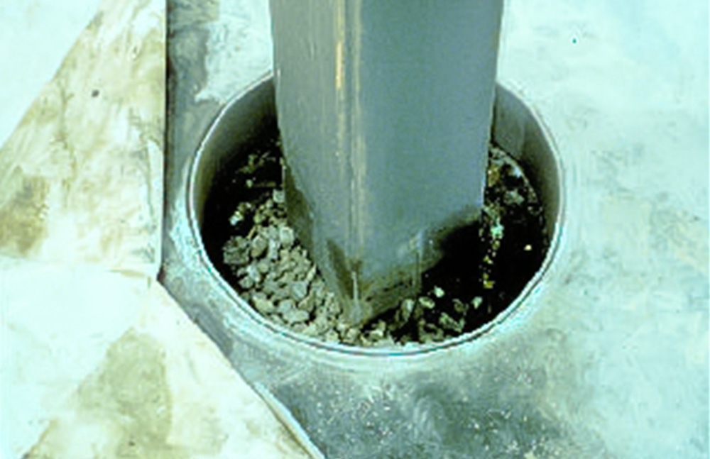
Column isolation sections were round instead of diamond-shaped due to many columns not being located on joints. Polyethylene foam plank was used for all isolation joints, instead of the typical asphalt-impregnated fiber filler, because the fiber filler was too strong and would not deform adequately. The foam filler was sized for the worst expected slab movement, plus a reasonable safety factor; however, joints were kept to the minimum feasible widths to minimize joint spalling. Isolation joints were sealed using an elastomeric urethane sealant, with close attention paid to proper sealant geometry and avoidance of three-point bonding. A semirigid epoxy joint filler was used in construction joints, except for armored joints that incorporated a silicone sealant for its superior extensibility.
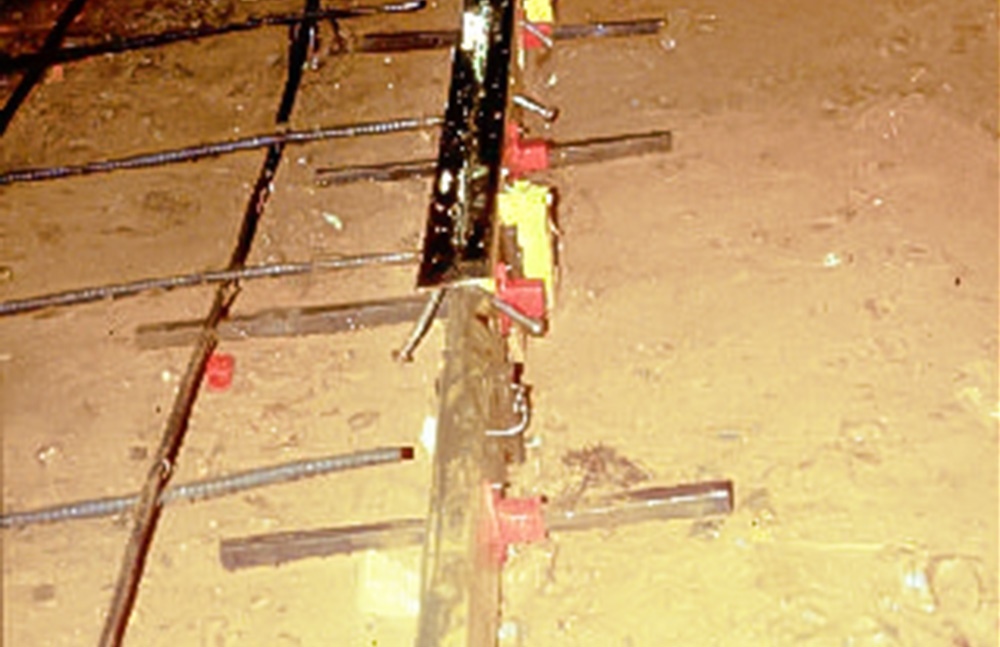
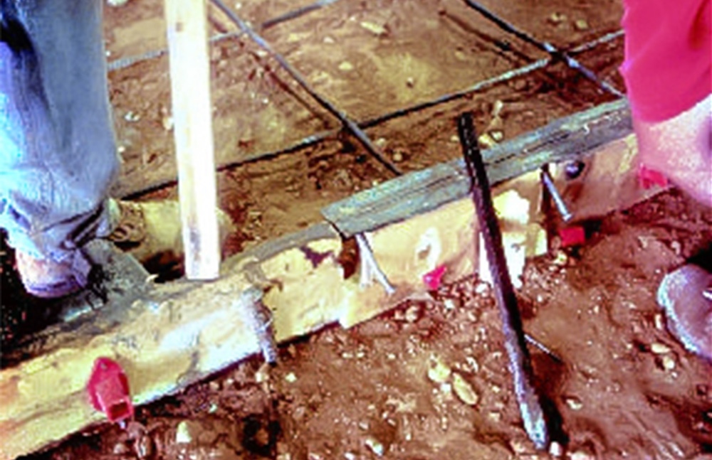
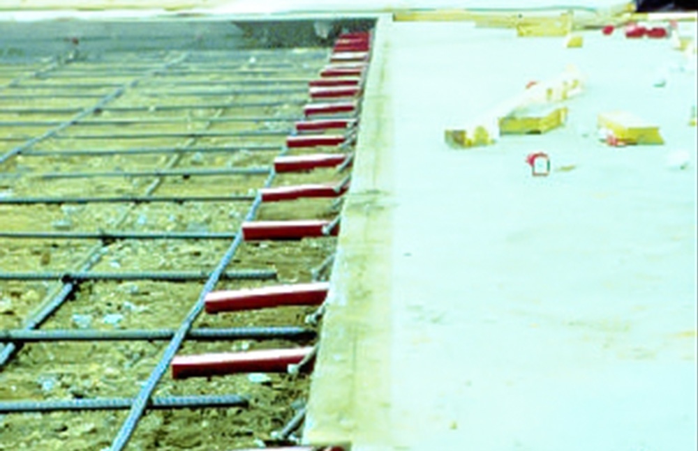
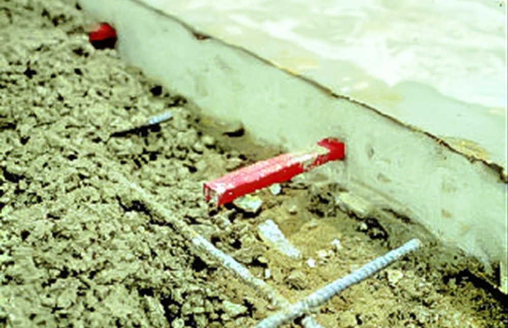
Kerfed shear keys are not positive means of providing load transfer between adjacent floor panels at typical joint spacings; therefore, smooth steel dowels were required. The significant differential movement expected for the SCC floor panels required ungreased, square (rather than round) dowels with cushioning side pads on clips to be specified in all locations. These padded, square dowels allowed horizontal differential movement between adjacent panels while transferring vertical loads. Close dowel alignment tolerances and other strict requirements were specified to minimize the possibility of dowel binding and the resulting slab problems.
The construction joints subjected to the most traffic were armored by steel edge angles incorporated into a unique prefabricated sideform and dowel aligner system. This system was produced by PNA, Inc., and used for all SCC forms on this project, whether the joint was armored or not. Some of the special features included the following very close tolerances, reusable dowel aligners already installed, and very straight-angles and anchors mounted on the forms. The angles have 1.5 in. (38 mm) legs and excellent anchorage, which eliminate the problems experienced for many decades with the commonly used much larger angles; they typically did not have good concrete consolidation under the horizontal leg and were not anchored sufficiently.
Floor slab structural data
The floor slab was 6 in. (150 mm) thick and had a single layer of No. 4 (12.7 mm) bars at 18 in. (460 mm) on center with 1.5 inc. (38 mm) concrete cover from the top of the slab. The reinforcing was for SCC purposes only, not for structural loading requirements. Specified concrete compressive strength was 4000 psi (28 MPa) at 28 days.
The SCC floor was designed such that it would support pallet loading for its initial use and rack loading in the future. Because a properly designed and constructed SCC floor has little or no edge curling, the very high curling flexural tension stresses usually occurring in PCC slabs (200 to 400 psi (1.4 to 2.8 MPa) curling stresses, as compared with a modulus of rupture of only 450 to 650 psi (3.1 to 4.5 MPA, typically) are not present. Lockwood Greene has developed a very unique computer program for slabs on ground that takes into account many variables not considered in traditional design methodologies, such as curl and shrinkage. This program indicated that if the slab had been designed as PCC with traditional procedures for future racks, it would have been 8 in. (200 mm) thick instead of the 6 in. (150 mm) SCC slab.
Concrete mixture requirements
Some requirements specified by the engineer for the concrete mixture may have never been used for SCC floors before, while others have been used only rarely. A few of these mixture requirements follow:
The following are advantages, as compared to a typical SCC concrete mixture for the same amount of expansion, derived from these specified requirements:
Extra mixture requirements added only slightly more cost than the typical ready-mix SCC cost. All parties involved with the project agreed that the very small extra cost was well worth it, and the floor subcontractor stated that this extra cost was at least partially offset by the reduced labor required.
Many favorable statements were made concerning the concrete mixture, including the following comments by key participants:
Bidding and preconstruction preparation
Unique floors, such as Gatorade’s, require special expertise for both design and construction. Few engineering or architectural firms have designed, and even fewer contractors have constructed, such cutting-edge floors. For this reason, a prequalified bidders list was prepared for the slab package, using only subcontractors with a proven track record of consistently producing specialty floors.
Lockwood, Greene, and Metric assisted the floor subcontractor (Frick’s Floor Systems) by maximizing constructibility and communication. Examples of this project teamwork are the following: scheduling the slab installation so that it could be done with the building enclosed and the roof membrane installed; specifying the mixture proportioning and ready-mix concrete quality-control requirements as noted above; and holding regular meetings, starting with the prefloor construction meeting.
Preparation for concrete placement
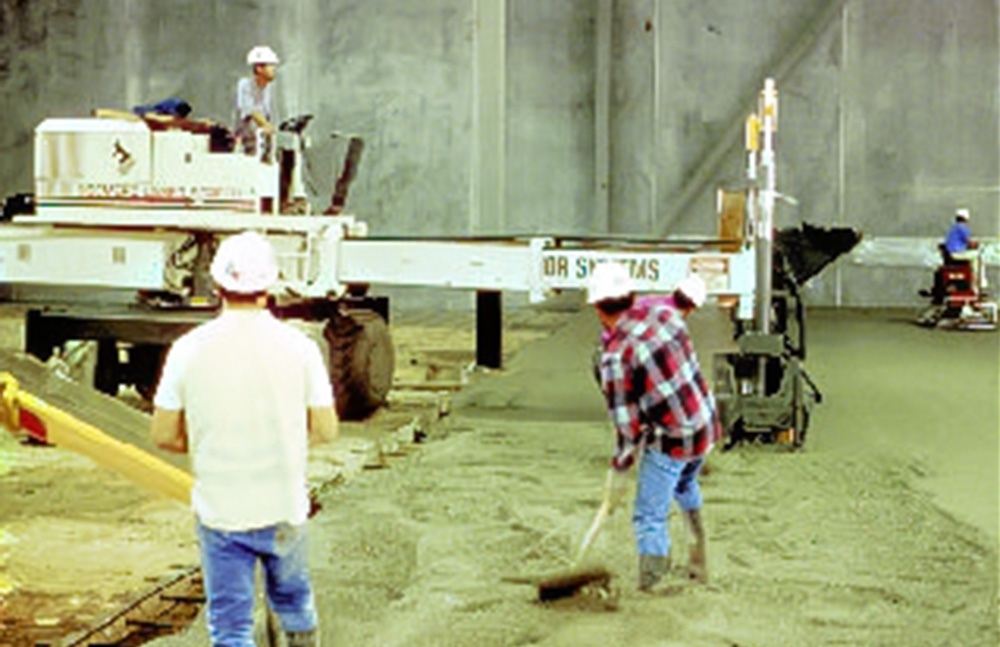
A good subgrade, important for all floors, is especially critical for such floors as this because of the close tolerances and heavy loads. A strong, uniform subgrade is imperative. The subgrade preparation was performed during a very wet fall and winter, causing difficult conditions. All possible measures were taken to ensure that the subgrade was of top quality; although, they involved extra cost and the possibility of significant delays to the project. These measures included replacing wet silty soils with more granular dry materials, the use of an easily compactable and trimable chrusher run as needed immediately under the slab to reduce subgrade drag, and close tolerance grading.
Side forms are crucial elements of a successful critical tolerance floor and affect most aspects of slab construction. If the tops of the forms are not sufficiently true, even the best finishers cannot meet the Fl tolerances. The floor subcontractor took several measures to ensure quality form construction. The forms were handled very carefully to prevent damage and were set at the correct elevation, straight, and plumb. During concrete placement, the elevation of the forms was constantly checked and, if necessary, readjusted, The resulting high F-numbers indicate the care taken with the forms.
Proper placement of reinforcing steel was extremely important. Reinforcing steel supports had to be the correct height, spaced closely enough, and adequately secured to steel bars. Steel mislocation due to improper installation or movement during concreting operations could cause significant cracking.
Concrete placement, finishing, and curing
Because of time constraints and economy, all of the concrete was tail-gated. Great care was taken to keep the concrete placement going at a consistent rate because even a short interruption can cause significantly lower F numbers and other problems.
To place the concrete by tail-gating and to use a laser screed for concrete strike-off and consolidation, the reinforcing bars were placed directly on the level, stiff base to allow the ready-mix concrete trucks and laser screed to roll over them. Between these vehicles and the just-placed concrete, the reinforcing-steel mat was lifted up and supported on chairs. By providing proper procedures for the reinforcing steel, they were not kinked by the wheel loads.
The laser screed is one of the greatest innovations in concrete floor construction in the last 15 years. It permits faster and larger concrete placements by allowing block placements rather than strip placements. Furthermore, it enables the contractor to have higher Fl numbers with less effort.
The concrete around the dowels was consolidated by poker vibrators. Good concrete consolidation is extremely important to provide proper dowel function.
A field-mixed trap rock hardener was applied at 1.5 lb/ft2 (7.3 kg/m2) in the high traffic areas. Trap rock is an extremely hard material and impart increased floor durability to the critical top 1/8 to 1/4 in. (3 to 6 mm) of the floor wearing surface. Field-mixing and installation of the hardener involves placing the well-graded trap rock aggregate in a small mixer, dampening it, adding cement so that each particle is slightly coated with the resulting paste, and working it into the floor surface evenly before the coated particles dry.
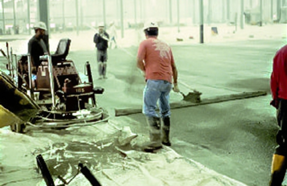
The tools, equipment, and procedures used for finishing the slabs played a major role in meeting the close tolerances. Long channel floats and 10 and 12 ft. (3.0 and 3.7 m) highway straightedges were used to provide close surface tolerances. The straightedges were used to cut down high spots and fill in low spots.
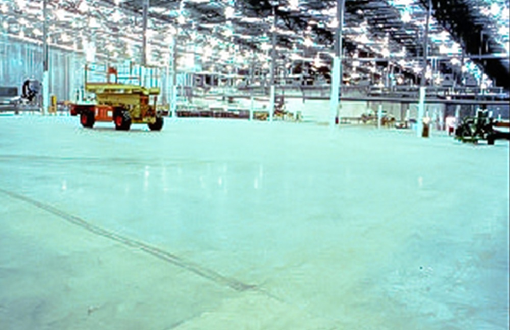
After initial floating of the slab surface, “pizza pans” were installed on riding double-trowels to enhance floor flatness. The floor was trowelled until it had a shiny, burnished appearance that has been found to be both very attractive and cleanable, highly desirable attributes for a beverage facility.
A special curing sheet was specified and was applied as soon as possible after completion of finishing operations. This curing sheet is a type that consists of a white, synthetic fiber mat (to hold extra curing water) with a white plastic sheet backing (to provide a very low-permeability barrier to moisture loss). This curing method and material were ideal for a SCC floor subjected to high abrasion and impact because of the following:
After the 7-day curing period was over, the sheets were removed and the floor surface allowed to dry. The cured concrete surface is so tight and dense that very little spilled liquid penetrates, as compared to normally constructed floors.
Monitoring flatness and levelness
As soon as feasible after the final trowel pass was made on a concrete placement, the surface tolerances were tested with a dipstick, allowing the contractor immediate feedback so that any changes necessary could be made for improvement. Many people mistakenly believe the only purpose of slab tolerance testing is to see if the contractor has met the specified requirements so they can penalize the contractor if he or she did not. Timely testing also serves as a check for the contractor to indicate needed adjustments.
Results
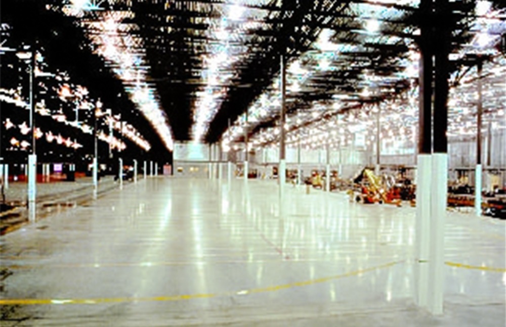
The Gatorade “very flat” floor has been very successful and has met or exceeded owner expectations. The specified FF 35 and FL 25 were exceeded by a consistent margin throughout the project. To put these values into the proper perspective, the average F-numbers for this project are approximately four times flatter and more level than the majority of the industrial slabs on grade now in use.
The future
Although the Gatorade floor is unique in some ways, many of the techniques and materials used may well become commonplace for the heavy-duty floor projects built in the future. As more design firms, material suppliers, and contractors get involved in these projects, they must keep abreast of the state-of-the-art techniques necessary to produce successful specialty floors. Furthermore, to minimize problems and maximize quality, owners, contractors, and engineers/architects must give the type of input and foster the kind of close teamwork that Gatorade, Metric, Lockwood Greene, and other participants provided on this project. Rather than the more typical adversarial relationship between team members, this positive teamwork produced successful results.
GATORADE PROJECT PARTICIPANTS
Owner: The Quaker Oats Company, Chicago IL; Engineer/Architect/Construction: Consultant Lockwood Greene Engineers, Inc. Atlanta, GA. Design-Builder: Metrick Constructors, Inc. Marietta, GA., A Division of J.A. Jones Charlotte, N.C.; Floor Subcontractor: Fricks Floor Systems, Inc., Fort Worth, Tex.; Concrete Supplier: Blue Circle Williams, Inc., Marietta, GA.; Type K Cement Supplier: Blue Circle Cement, Inc, Marietta, GA.; Specialty Floor Products Supplier: PNA, Inc., Mathews, N.C.; Slab Tolerance and Concrete Testing Geotechnical Engineering and Testing: Law Engineering & Environmental Services, Inc. Atlanta, GA.
Written by: Donald A. Bailey, Edward J. Barbour, Scott W. Cupp, Jerry A. Holland, and David W. Knight.
Donald A. Bailey is a civil engineer serving as a senior project manager with Metric Constructors in Marietta, GA., a division of J. A. Jones. He has over 20 years of experience in managing many types of construction projects, including industrial, commercial, and institutional facilities. Bailey has managed several projects for the Quaker Oats Company.
Edward J. Barbour is a structural and civil engineer serving as a principal engineer with the Gatorade/Beverages Division of the Quaker Oats Company. He has over 20 years of experience in the design and construction of beverage and food facilities. Barbour covered the civil, structural, and architectural portions of this project for Gatorade.
Scott W. Cupp is a chemical engineer serving as a project manager with the Gatorade/Beverages Division of the Quaker Oats Company. He has over 20 years of experience in the construction and operations of beverage and food facilities in the United States and international locations. Cupp was the project manager for this project for Gatorade.
Jerry A Holland, FACI, is a structural engineering consultant with Lockwood Greene Engineers and Architects in Atlanta, Ga. He has 33 years of experience in design, construction, and troubleshooting concrete materials and structures. Holland is past chairman of ACI Committee 360, Design of Slabs on Ground, and is currently a member of that committee; as well as 223, Shrinkage-Compensating Concrete; 301, Specifications for Concrete; 302, Construction of Floors; and 350, Environmental Engineering Concrete Structures.
David W. Knight is senior structural engineer with Lockwood Greene Engineers and Architects in Atlanta, Ga. He has 20 years of experience in all types of structural engineering, including specializing in writing computer programs and performing analysis and design of complex structures. Knight is a member of the STADD Steering Committee and is Chairman of the Graphical Interface Sub-Committee.
CTS Cement Manufacturing Corp. is the leading manufacturer of advanced calcium sulfoaluminate (CSA) cement technology in the United States. Our Komponent® and Rapid Set® product lines are renowned for proven performance, high quality, and exceptional service life. Contact CTS Cement for support on your next project.
Call 1-800-929-3030.
Original publication: Bailey, D., Barbour, E., Cupp, S., Holland, J., and Knight, D.,(2002, January). Article published in ACI.