Construction began on Parking Structures A2 and B2 at John Wayne Airport in Santa Ana, CA in the early 1990s. Virtually everyone in the Southern California construction community during that period was aware of the project because of its dramatic RTS cracking problems and the ultimate resolutions.
The buildings are framed with cast-in-place, monolithic post-tensioned concrete slabs, beams, and girders. Each contains three elevated levels (L1, L2, and L3), and each is three bays wide (about 175 feet) in the direction of the beam spans, and very long (over 1,000 feet) in the direction of the slab spans. The long direction is separated into independent sections, each slightly over 300 feet in length, with two permanent expansion joints. Each independent section has two pourstrips.
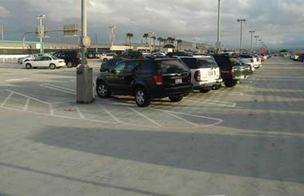
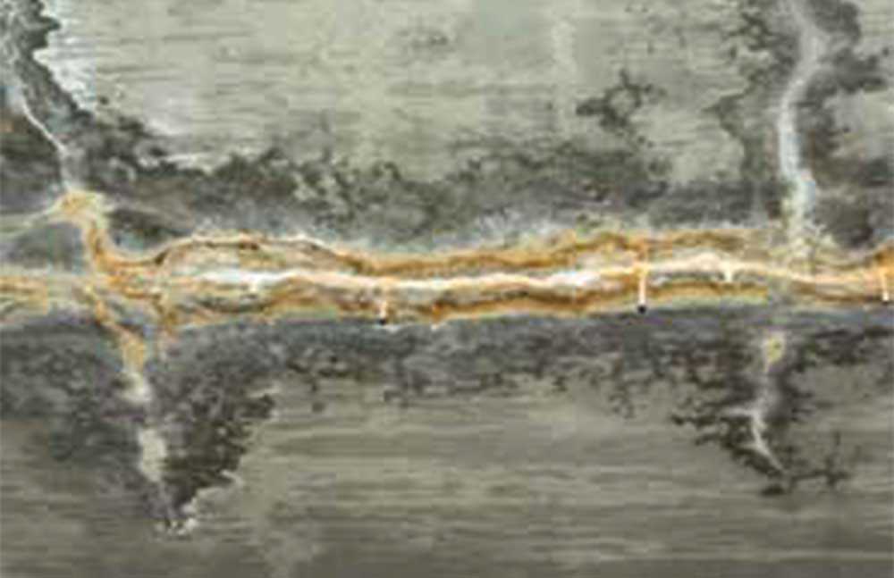
The buildings were built in two phases: first an initial level (L1), and then two upper levels (L2 and L3) as the need for additional parking arose. The first elevated level (L1), built with normal-weight portland cement concrete, was completed in the early 1990s and immediately began to crack severely. Eventually, over 70,000 linear feet of cracks were measured and repaired in the 480,000 square feet of floor area in both structures. Prior to repair, some of the cracks allowed the passage of water through the slab, resulting in unsightly efflorescence at the slab soffit and potential damage to cars below (Figure 1).
Construction proceeded on the upper two levels in the late 1990s. The most significant structural change made in the upper levels was the use of Type K shrinkage-compensating concrete. Virtually all other details relating to RTS were unchanged: dimensions, pourstrips, joinery details, and the contractor executing the work. The two expanded structures were completed and went into service in 1998.
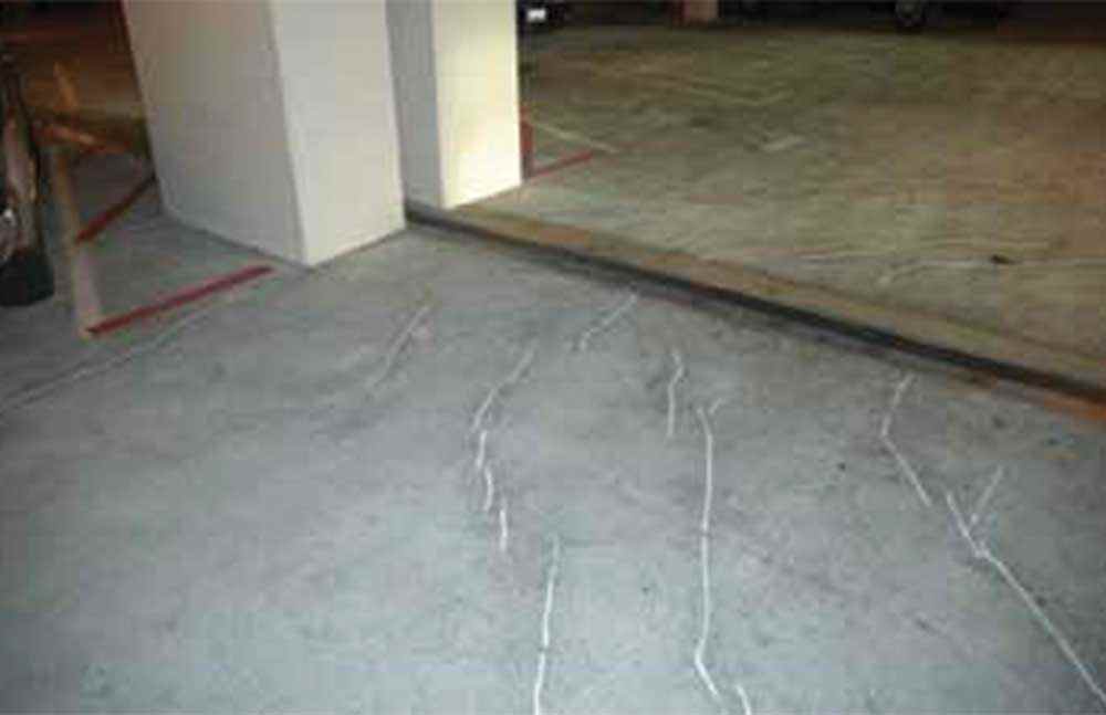
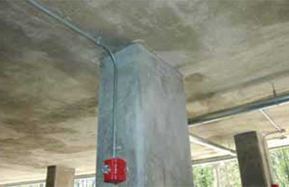
A visual inspection of all three elevated levels of both structures was made in February 2009, about eleven years after completion of the second phase. There is a striking difference in the performance of the upper levels (L2 and L3) where shrinkage-compensating concrete was used, and the lower level (L1) where it was not. The L1 level is laced with thousands of feet of unsightly repaired cracks (Figure 4). The upper two levels, L2 and L3, are virtually crack free. Since the only significant and relevant variable is the use of shrinkage-compensating concrete in the upper levels, the performance difference can be reasonably attributed to the cement.
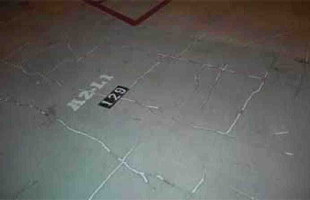
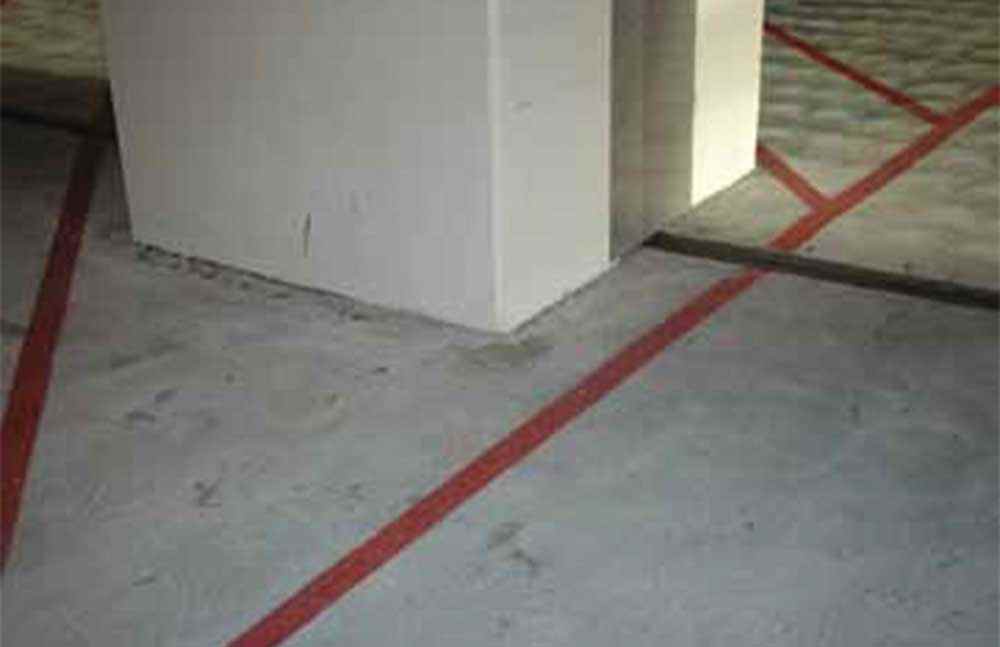
Figure 3 shows the top of the slab at a double column straddling the expansion joint at the L1 level. Diagonal cracks radiate off the columns in an orientation consistent with RTS on either side of the expansion joint. Figure 4 shows the top of the slab on the L2 level, exactly one floor above the location shown in Figure 6. The slab is crack free at this location.
Ridgecrest Community Residence, University Of Alabama, Tuscaloosa
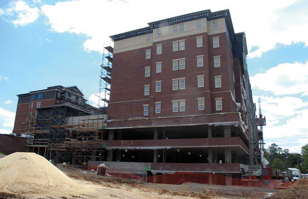
The building is an 8-story student dormitory and parking structure built on-campus for the University of Alabama in Tuscaloosa. In this building, the use of shrinkage-compensating concrete resulted in the elimination of pourstrips in large post-tensioned slabs with cost savings and excellent performance.
All of the floors are framed with cast-in-place post-tensioned flat plates (solid thickness slabs supported on concrete columns with no drop panels or shear caps). The lower three elevated slabs are roughly 650 by 300 feet in plan dimension, separated by a central permanent expansion joint running in the 300’ dimension. The slab-on-ground and the first two elevated slabs (7¼ inches thick) are used for parking; the third elevated deck (11-12 inches thick) is the first residential floor and forms two large courtyard areas with landscaping. Type K cement was used in the lower three slabs but not in the upper residential slabs (7¼ inches thick) where Type 1 was used (with pourstrips).
The photograph in Figure 5 was taken in April, 2009 when the building was structurally complete but architectural finish work was still underway.
The original design of the building used light steel framing in the upper residential floors. Bearing walls were supported on the third floor concrete deck on a grid of deep concrete transfer beams, with a post-tensioned slab outside and between the beams. On the lower two elevated parking slabs, each of the two 300 by 300-foot pieces were divided temporarily into four smaller pieces by pourstrips, specified to be kept open for 9 to 12 weeks.
Bids came in substantially over the approximately $70 million budget. The structural engineers, Structural Design Group (SDG) of Birmingham, AL, value-engineered the job for cost-cutting measures. They eliminated steel framing and changed to post-tensioned concrete slabs in the upper residential floors, using the same column layout as the parking area below. That eliminated the grid of transfer beams at the third level. They used Komponent® shrinkage-compensating concrete in the lower three elevated slabs in order to eliminate pourstrips. This resulted in direct savings in the cost of building pourstrips, and a significant savings in construction time. SDG did a complete redesign of the building based on these and other cost-saving measures.
Bids on the redesigned job came in under budget. Net savings realized by eliminating pourstrips was estimated at $250,000, including the premium for the KSC concrete. Total savings realized by the redesign was about $3 million.
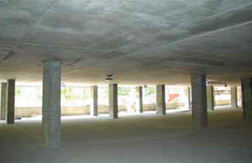
Construction started in 2007 and the building was completed in 2009. During an onsite inspection of the parking level slabs in April 2009, they were found to be in excellent condition. No cracking was evident related to RTS or applied load. Careful observation of the far corners of each of the sections separated by the expansion joint – where the most RTS cracking could be expected – revealed these critical areas to be crack-free. An experienced observer of post-tensioned slabs would rate the performance and condition of these large slabs as outstanding.
In a published article describing the building, the structural designers state:
“The real proof is the slab itself – there are virtually no cracks in more than 420,000 square feet of slab. Further, the concrete frame was bid and completed 42 days ahead of (a very aggressive) schedule.”
The first elevated slab of this building was extensively instrumented to measure short and long-term concrete strains and curvatures. The testing program was directed by Dr. Jim Richardson, professor of Civil Engineering at the University of Alabama. Data collected 14 months after construction of the slab has been published in the ACI Structural Journal.
Measurements made 14 months after the slab concrete was placed show that total shortening in the first-floor slab (0.000435 in/in) was less than half that predicted for conventional (i.e., non-shrinkage-compensating) concrete normally used for this application. That is extremely significant, since studies of concrete shrinkage versus time show that over 80% of total shrinkage has occurred at 14 months, and the remaining 20% progresses with dramatically decreasing rate over the next 20 years. If it is assumed that another 10% of the final total strain will occur between 14 months and 5 years, predicted total strain at 5 years would be 0.000435/0.9 = 0.000483 in/in., a value reasonably consistent with the 5-year strain of 0.00034 in/in measured in the Santa Monica Structure #2. Continuing strain measurements made on the Ridgecrest structure should lead to important new information on creep relaxation and temperature change effects.
This is an extremely important building whose significance cannot be overestimated. Its success will help establish a relationship between post-tensioned concrete and expansive concrete that should have a great impact on future design and construction practices. Things were done in this building that could not have been done without the use of shrinkage-compensating concrete, and they resulted in outstanding performance and significant cost savings.
CONCLUSION
RTS (along with tendon corrosion) is one of the two biggest problems ever faced by the post-tensioning industry. Looking back over the growth of post-tensioned concrete for 5 decades, and the early efforts to solve the shortening problems, it seems that the use of shrinkage-compensating concrete may have made the solution to the RTS problem easier.
Observations of the four buildings included in this survey (including the two discussed in the April 2010 issue) indicate that, on most post-tensioned concrete buildings, the use of shrinkage-compensating concrete (when properly mixed, placed, finished, and cured) can substantially eliminate pourstrips; and, with due consideration of temperature effects, can realistically increase the maximum length between expansion joints to approximately 500 feet, with equivalent or superior performance.
The author gratefully acknowledges the staff of CTS Cement Manufacturing, Inc., whose products include Komponent® shrinkage-compensating cement, and in particular its president, my old friend Ed Rice, for their assistance with this article.
Written by: Michael Chusid, RA FCSI. Kenneth B. Bondy, S.E., FACI, is the current President of the Post-Tensioning Institute (PTI) and was, in 2005, inducted into the PTI Hall of Fame, Legends of Post-Tensioning. He serves on numerous ACI committees. Mr. Bondy can be reached at www.kenbondy.com.
CTS Cement Manufacturing Corp. is the leading manufacturer of advanced calcium sulfoaluminate (CSA) cement technology in the United States. Our Komponent® and Rapid Set® product lines are renowned for proven performance, high quality, and exceptional service life. Contact CTS Cement for support on your next project.
Call 1-800-929-3030
Original publication: Chusid, M. (2011, January). Use Of Shrinkage-Compensating Concrete In Post-Tension Buildings. Structure Magazine. 27-29.
REFERENCES
Chusid, M., A Perfect Match: Post-Tensioning and Shrinkage-compensating Concrete Form a Durable Union at John Wayne Airport, PTI Journal, Post-Tensioning Institute, July 2007, pp. 77-82.
Eskildsen, S., Jones, M., Richardson J., No More Pour Strips, Concrete International, American Concrete Institute, October, 2009 pp. 42-47.
Richardson, J., Eskildsen, S., Schiller, B., and Jones, M., Measured Strains in a Post-Tensioned Concrete Parking Deck, pending publication in the Structural Journal of the American Concrete Institute.
Bondy, K. B., Post-Tensioned Concrete in Buildings: Past and Future – an Insider’s Viewpoint, PTI Journal, Post-Tensioning Institute, December, 2006, pp. 91-100.
Part Two: A Four-Building Survey
This is the second of a two-part article presenting case studies of four projects which demonstrate the effective use of shrinkage-compensating concrete to mitigate restraint-to-shortening (RTS) cracking in post-tensioned concrete buildings. Two of these projects were built more than 40 years ago, one has been in service for 12 years, and one is new, completed just 19 months before this writing. The first two buildings surveyed were presented in the April, 2010 issue of STRUCTURE magazine.